One of the most frequent electrical tests performed both in residential and industrial settings is the insulation resistance test. It measures the resistance between any two points in an electrical circuit to determine the condition of the insulation. In simple terms, it assesses the insulation in wiring, cabling, switches and switchgear, appliances and motor windings in equipment and machinery. But to better understand insulation resistance testing, one first needs to know the role of insulation.
Understanding the Importance of Proper Insulation
The role of insulation is to resist current and to keep that current on its path through the conductor. Any faults in the insulation can be a potential safety hazard and the cause of equipment failure. In residential settings, this can lead to electrical shock, and in industrial settings, it is often the reason for costly repairs.
So, what makes “good” insulation? Insulation with high resistance to current and the ability to maintain that high resistance is considered to be good insulation. This means that the current doesn’t leak at any point within the electrical circuit. However, certain factors can lead to the deterioration of insulation. Changes to temperatures, exposure to humidity, moisture and liquids, damage from mechanical stress or vibration, oil, chemicals and dirt all affect its quality over time. To determine whether cables, wiring, appliances or equipment have sound insulation and if there is a sudden or gradual drop in insulation resistance, electricians conduct an insulation resistance test.
What Are Insulation Resistance Testers?
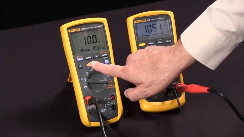
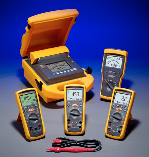
Insulation resistance tests are carried out using small, hand-held devices called insulation resistance testers, basically high resistance ohmmeters, that have built-in generators to produce a high voltage DC current. The voltage ranges from 500V to 12kV. A specified voltage is passed through the surface of the insulation to measure the resistance value. Higher readings, often in MΩ or Mega-Ohms and GΩ or Giga-Ohms, indicate that the condition of the insulation is good. Lower readings often are a sign of damage or fault.
If you’re browsing the array of insulation resistance testers, you’ll notice that they range from basic megohmmeters, or meggers that suit low-voltage applications up to 1000V, to specialised testers able to generate 15kV and suitable for testing insulation in cabling, motors and equipment in high voltage industrial settings. Readings are displayed either digitally on an LCD screen, or as analog values against set Ohm scales.
How Is an Insulation Resistance Test Done?
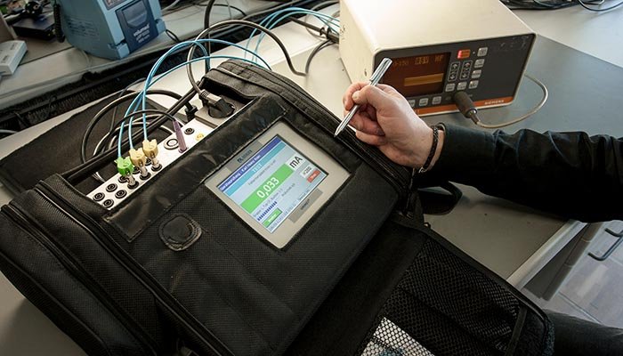
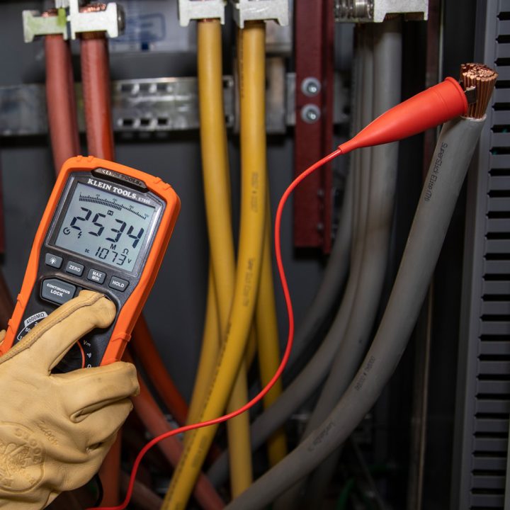
During an insulation resistance test, the “line” or “L” terminal of the insulation resistance tester is connected to the conductor where the insulation is being tested. The tests are performed with the circuit de-energised.
The “earth” or “E” line is connected to the insulation itself. Another terminal, the “guard” or “G” terminal is used to provide for a return circuit that bypasses the tester and is used to disregard the current form connected circuits. A stable current is conducted for a specified time from the tester through the conductor and insulation, and the resistance values are displayed at the end of the testing cycle.
Types of Insulation Tests
There are three basic tests carried out with an insulation resistance tester: a spot-reading test, a time-resistance method, and the dielectric absorption ratio.
Spot reading tests are conducted for up to 60 seconds and provide for a rough guide as to the state of the insulation. This is because of capacitance charging current that starts out high, but drops as the insulation reaches full voltage. For home wiring this test is more than enough to conclude whether the insulation is “good” or faulty. For larger installations and equipment further testing will give more precise results.
Time resistance tests take into account absorption current, or the current absorbed by the insulation when a set voltage is applied. This method consists of multiple readings done at set time intervals and comparing the resistance values. If the values increase in each successive test, then the insulation can be deemed as “good”. This is a general maintenance measure used in industrial settings to evaluate the condition or wiring, motors, switchgear and more.
The dielectric ratio is the resistance value between two individual readings in successive tests and is used to determine whether the insulation is deteriorating or external factors are at play.
Interpreting Readings
It is the electrician’s job to interpret the readings during an insulation resistance test. As a general rule, higher readings mean that the insulation is up to the task, whereas lower resistance readings are a sign or trouble. Frequent testing is required to detect any drop in values and detect any issues.
Different factors, like changes in temperature and humidity can affect the readings during the test itself. To get consistent results, subsequent tests should be conducted at the same temperatures and humidity levels. A rise in temperature decreases overall insulation resistance and readings are lower. In settings with high humidity, a drop in resistance values can be a sign that cracks are forming in the insulation.
A general rule is that insulation resistance should be one megohm for each 1000 Volts of operating voltage, with a minimum value of one megohm. For example, motors and equipment that operate at higher voltage, like most in industrial environments, will have higher values. A motor with 3000V should have a minimum insulation resistance reading of 3 megohms.